FigTronix: Difference between revisions
| Line 64: | Line 64: | ||
[https://oshpark.com/shared_projects/m3Ugar47 PCB]<br> | [https://oshpark.com/shared_projects/m3Ugar47 PCB]<br> | ||
(todo, link to parts order) | (todo, link to parts order) | ||
:low profile SMT plcc32 socket | :[[http://www.digikey.com/short/32dc2q low profile SMT plcc32 socket]] | ||
:28F256 plcc32 | :[[https://www.aliexpress.com/store/product/Free-Shipping-AM28F256-150JC-AM28F256-28F256-PLCC-PLCC32-100-NEW/1390498_32734330044.html 28F256 plcc32]] | ||
:tape | :Other materials | ||
::1/2" double sided tape | |||
::3/8" ribbon | |||
::paperboard (IE cut from ceral box) | |||
This one is the all around simplest to use, but the one drawback is just that it's more finnicky/tricky to build. Because you have to use solder paste and hot air. You can't directly access the pins to fixup any errors. All you can do is heat it all up and take it off, clean up up, and start over. | This one is the all around simplest to use, but the one drawback is just that it's more finnicky/tricky to build. Because you have to use solder paste and hot air. You can't directly access the pins to fixup any errors. All you can do is heat it all up and take it off, clean up up, and start over. | ||
Also if you don't sand the socket down enough, then the plcc socket will push the pins in the M100 socket away from the module and the module won't work. Then you have to fiddle with not inserting the module too far into the M100 socket to get a good connection. If this happens, you might be able to address this without having to start over, by adding another layer of paperboard spacer underneath. | Also if you don't sand the socket down enough, then the plcc socket will push the pins in the M100 socket away from the module and the module won't work. Then you have to fiddle with not inserting the module too far into the M100 socket to get a good connection. If this happens, you might be able to address this without having to start over, by adding another layer of paperboard spacer underneath. | ||
Revision as of 16:40, 18 March 2017
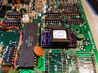
Model 100 Main ROM 27C256 PLCC Adapter
This is ONLY for early Model 100's that had a weird main rom pinout, with chip number LH535618.
Late Model 100's and all Model 102's had a standard 27C256 pinout and don't need any adapter.
About the parts order:
- It includes enough parts to build 3 boards, because you can't get less than 3 PCBs from OSHPark. If you want to build just one board, reduce the quantities by 2/3.
- It includes several extra 27C256 eprom chips, because they are one-time-programmable, not erasable. I just picked 10 as a generous round number. You can order as few as one chip per board, if you know you will get the programming step right the first time.
- Or, if you can find some uv-erasable ones, you can use just one of those, and omit the eproms from the DigiKey order. You can't get new uv-erasable 27C256 in plcc packaging today, but you can possibly find old stock or used ones. Like these:
- http://ebay.com/itm/390797004761
- http://ebay.com/itm/121899875951 (actually, I'm not sure this 2nd kind would work in the socket. Try at own risk. I got the first kind and they work.)
Unfortunately, using this adapter requires desoldering the original socket from the motherboard. It IS possible to do this, without damaging either the motherboard or even the old socket, with flux, solder wick, and patience. Search youtube for "desolder dip".
TODO: Replace this design with one that uses a low profile surface-mount plcc32 socket 28C256. Doing that will mean we have an erasable, reprogrammable part, and it should fit in the original dip socket so we don't have to desolder it. If the combined height of the low profile pin headers and low profile plcc socket are still too thick, then try to find a supplier for edge-clip legs instead of pin headers. Or we can try soldering the pin headers in backwards with just the tips of the long pins soldered in the adapter, and then cut the shoulders and short-sides right off all pins. That will leave you with bare pins with no shoulders, so the board should fit closer to the socket, and maybe that will be enough .
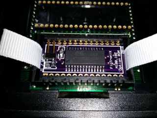
Model 100/102/200 Option ROM adapter (SOIC 28C256)
- 1/2" double-sided tape
- 3/8" ribbon
- paperboard (IE: cut from cereal box)
This is parts enough to build all 3 boards you get from OSHPark.
Options
You can reprogram 3 different ways:
1
- Using a special programming adapter (another FigTronix PCB below) with a Molex socket that you can snap the module into the same way it snaps into the M100
- U1 is pin headers. Install 2 rows of 14 pins on the bottom side of the board (the side without the silkscreen).
- U2 is a Molex socket the same as what's in the Model 100. Contact Brian bw.aljex@gmail.com for one. I have about 100 that I'll give away until gone.
2
- Using a DIP28 test clip, clipped to the outside edges of the module. In this case, you need to re-arrange the wires from the programmer to the test clip to essentially reverse the re-arranging that the adapter module does.
3
- Using a SOIC28 test clip, clipped right to the eprom on the board. In this case, you can omit the write-enable jumper pins from the board, and the wiring from the programmer to the test clip is normal 1:1 2:2...28:28.
Usage
In normal usage, whenever the module is installed in a M100/102/200, do NOT short the two pins with the jumper.
Install the jumper only while flashing a new rom.
If you are programming with a SOIC28 test clip, then neither of these applies.
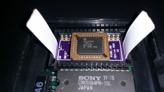
Model 100/102/200 Option ROM adapter (PLCC 28F256)
PCB
(todo, link to parts order)
- [low profile SMT plcc32 socket]
- [28F256 plcc32]
- Other materials
- 1/2" double sided tape
- 3/8" ribbon
- paperboard (IE cut from ceral box)
This one is the all around simplest to use, but the one drawback is just that it's more finnicky/tricky to build. Because you have to use solder paste and hot air. You can't directly access the pins to fixup any errors. All you can do is heat it all up and take it off, clean up up, and start over.
Also if you don't sand the socket down enough, then the plcc socket will push the pins in the M100 socket away from the module and the module won't work. Then you have to fiddle with not inserting the module too far into the M100 socket to get a good connection. If this happens, you might be able to address this without having to start over, by adding another layer of paperboard spacer underneath.


