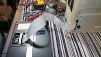
Disk/Video Interface: Cable
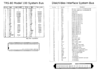
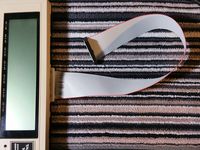
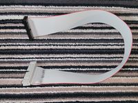
Special cable for Disk/Video Interface
For Model 100
Parts:
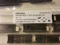
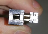
- 40pin DIP idc connector
- 40pin female idc connector, with polarity notch and strain-relief
- 40pin ribbon cable, 20 inches
Assembly:
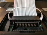
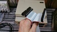
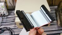
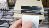
- Crimp the cable in the DIP connector such that if you are looking at the dip connector with the #1 pin top-left and pins pointing away from you, the cable exits to the right, red stripe on top.
- For the DVI end of the cable...
- This assumes you ordered the actual DIP connector linked above, or have another one that connects it's pins to the conductors in the same pattern. Not all do. See note below.
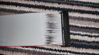
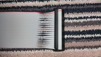
- Grab the red wire and the one next to it as a single pair, and peel the pair away from the rest of the cable for about 2 to 3 inches. Repeat for the rest of wires, so the cable ends in 20 loose pairs.
- Take the 1st pair of wires (the one with the red stripe), and twist it 1/2 way so the wires are reversed. Insert this pair into the IDC connector in the 1st 2 wire positions at the pin 1 end of the connector. Hold this pair in place by holding a light pressure on the idc connector, enough to keep the wires from falling out, but not enough to prevent you from inserting tbe next pair of wires.
- Repeate this process for the next pair of wires, and all the rest.
- When all 20 pairs are inserted, Wiggle the cable alotle while applying light pressure on the idc connector to settle all the pairs into perfect alignment before crimping.
- Crimp. (I use a small table top hobby vice. Have the jaws open just enough for the connector to fit. While maintaining pressure on the connector to hold all the wores in place, slide one end of the connector into the jaws, and tighten the jaws untill the connector is stiff but still able to slide the rest of the way into the jaws. You want the vice to take over the job of keeping enough pressure on the wires so they don't fall out. Slide the connector the rest of the way into the vice. Check the wires one last time, wilggle, push pull as necessary so they are all in position and none of the pairs is shorter or longer than the others. Then tighten the jaws to crimp the connector all the way.)
- Fold the wires over the back of the connector and add the strain relief clip to the crimped connector.
NOTES
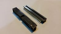
- Most DIP IDC connectors connect wire 1 to pin 40, and wire 2 to pin 1. This is almost guaranteed to be the only kind you can get today. For instance:
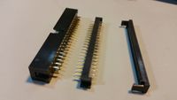
- Various makes of DIP IDC connectors
- All of these connectors require twisting every 2 wires in the cable.
- But at least one version of the original cable from Tandy had a special version of the connector where wire 1 connected to pin 1, and wire 2 connected to pin 40. That special connector doesn't need any twists in the ribbon cable.
- It's theoretically possible you might find that kind of connector, in which case you should not split and twist the wires.
- More sources for crimp-on dip40 plugs
For Model 102
Parts:
- 40pin boxed male idc connector, with polarity notch
- 40pin female idc connector, with polarity notch and strain-relief
- 40pin ribbon cable, 20 inches
Assembly:
- Crimp the male connector on one end of the cable. Make sure the red wire goes on the Pin-1 marker on the connector, and ideally put the polarity notch at the end of the cable.
- On the other end of the cable, same as for the DVI-end above for Model 100.
- (TODO: Make a new cable and update pics reflecting the following notes.)
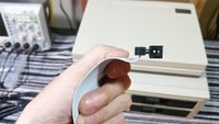
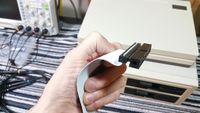
- Note: These pictures show the wires twisted on the computer end instead of the DVI end. It actually doesn't make a difference where you put the twists, electrically. But it's better to put the twists on the DVI end for a few reasons. The twisted end of the cable is weaker, because the wires have been seperated from each other, making it more likely for individual pairs to have their connections weakened from pulling.
- Neater looking. The twists are hidden under the DVI.
- The DVI end suffers a less flexing than the computer end, because the computer moves around more than the DVI, and the computer end of the cable is handled more than the DVI end.
- The female connector on the DVI end has a strain relief clip.
- The socket in the DVI has latches that eject the connector out without having to pull on the cable.
For Model 102 and 200
Original/Official Cable for Tandy 102 and 200
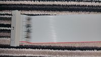
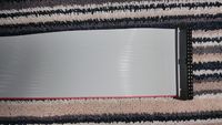
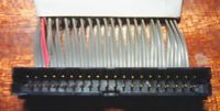
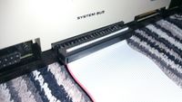
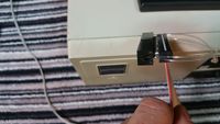
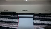
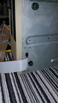
The actual original cable for Model 102 & 200 looked like this on the computer end. You can't get exactly that size of connector today in a crimp-on form. The crimp-on connector you can get today is longer, and fits in a Model 102, but does not fit in a Model 200.
Good Cable
Here is one method to make a good cable that:
- Doesn't require splitting the ribbon cable up into 20 pairs and twisting each pair.
- Includes a shroud around the male pins that actually fits in the system bus connector opening in a Model 200.
- Is polarity-keyed on both ends.
The down-sides are:
- Have to solder two parts together, and it's a little fiddly & annoying to solder two sets of plain pins to each other, and work in the small gap between the two plastic parts.
- There is no strain-relief for the crimped connection on the computer end of the cable, so pulling on the cable to unplug it from the computer will weaken or break the contact between the wires and the pins in the crimp-on connector.
Pay attention to the orientation of the red stripe when crimping, consult the pictures below. The red stripe goes with the pin 1 mark on both the female IDC connector and on the boxed male header connector.
Soldering the two connectors back-to-back takes the place of having to twist every pair of wires.
DigiKey parts order: http://www.digikey.com/short/jhqvwf
Step 1: Solder the "wire-to-board aka "transition" connector back to back to the boxed male header connector.
Step 2: Hold the soldered assembly with the polarity notch up, and looking at the back of the crimp connector where the cable will go. Place the cable with the cut end up and the red stripe to the left (red stripe goes with the pin 1 mark on the boxed male header connector). Crimp the cable in the transition connector.
Step 3: Make a pull handle for the computer end of the cable by feeding a double loop of heavy fishing line the long way between the two rows of soldered pins between the two soldered connectors. Use enough line to make a double loop large enough to put 2 or 3 fingers inside the loop. Tie the ends together. Trim the excess line ends to within 1/4" of the knot. Melt the cut ends down to the know and melt the knot a little too.
Step 4: Crimp the female idc connector with strain relief on the other end of the cable, red stripe on the pin 1 mark.
Easy Cable
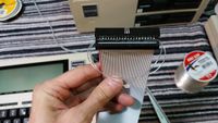
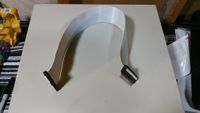
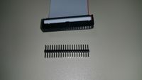
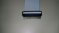
The simplest way to make a working cable for Model 102 or 200 is to use a cable with female IDC connectors on both ends (most ordinary IDE cables work), and then add a gender-changer male pin header to the computer end.
This is not ideal, because the resulting assembly is not polarity keyed (allows you to plug it in backwards or upside down, or offset by one row), and the male pins are not protected from shorting or bending.
But it's very simple to put together, especially if you use an ordinary IDE cable, you don't even have to crimp the connectors yourself. Just buy the pin header and stick it in any common pre-made IDE cable.
You should glue the pin header in to the IDE cable, just a tiny bit of super-glue on the black plastic parts, try not to let it run into the metal parts. This is so that when you un-plug the cable from the computer, the pins stay with the cable instead of staying in the computer.
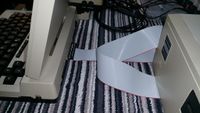
This cable is not polarity keyed. Pay attention to the orientation of the red stripe in these pictures. It's up to you to plug it in the right way and never get it backwards by mistake!
Also for the IDE cable, watch out for some cables that won't work.
- Use a 40-wire cable not 80-wire
- Some IDE cables have a pin missing, or plugged. You need a cable with all 40 pins.
- Some IDE cables have one of the wires cut somewhere along the cable. It looks like a tiny oval hole punched in the cable. They are not common but they do exist, and so you need to make sure you don't use a cable like that.
More Pictures for Model 102/200 Easy Cable
Quick-n-Dirty neat trick
Another way to get the wires crossed the right way (instead of that tedious and finnicky peeling & twisting 20 pairs), is just join 2 ordinary female idc connectors with a double ended male-male idc pin header. The arrangement of the connectors matters, and the rule is just match up the red stripe from both cables. Thanks Mike Stein for this trick.
What this means exactly is, to use this trick:
- To make a cable for Model 100:
- Make 2 cables. One with a DIP IDC on one-end and a regular female IDC on the other end, and another with regular female IDC connectors on both ends. Orient the red stripes on both cables with the Pin #1 marks on all connectors. Crimp all connectors on normally, with no twists in the wires anywhere. Join the two cables with a single double-sided pin header, keeping the red stripes from both cables aligned. This creates a working cable, where the double-sided straight-through pin header joining the two female connectors face-to-face ends up having the same effect as twisting the pairs of wires.
- To make a cable for Model 102 and 200:
- Same as the 3-part cable above for Model 100, except omit the cable with the DIP IDC on it, and just keep the cable with two regular female IDC connectors and the double-sided pin header. Simply take the cable with the two regular female IDC connectors and the double-sided pin-header, and plug the double-sided pin header right in to the 102 or 200. Pay attention to the orientation of the red stripe. The cable should stay in the same orientation as it comes out from under the DVI, as if it layed flat the whole way to the computer. The red stripe should be towards the side of the computer with the power switch. This is actually exactly the same as the "Easy Cable" above.
