Building a REX: Difference between revisions
No edit summary |
|||
| Line 1: | Line 1: | ||
[[File: | [[File:20190730 232012.jpg|800px]] | ||
=Introduction= | =Introduction= | ||
Building Steven | Building a REX, BKW version.<br> | ||
This is essentially a REX1 with a modified pcb layout from Steven Adolph's original.<br> | |||
Electronically identical.<br> | |||
Software identical.<br> | |||
PCB shaped to snap into a 3d-printed carrier, and provide connections for power and PORT_EN for programming the CPLD. | |||
==Parts & Materials== | |||
*[https://oshpark.com/shared_projects/DKF7eN1c PCB] | |||
*[http://www.digikey.com/short/qtqhcf Electronic Components] (or [http://www.digikey.ca/short/qtqr90 In Canada]) | |||
==Parts | |||
*[http://www.digikey.com/short/qtqhcf Electronic Components | |||
: If the flash memory chip is on backorder: [[REX:flash|How to Identify a Compatible Flash Chip from Elsewhere]] | : If the flash memory chip is on backorder: [[REX:flash|How to Identify a Compatible Flash Chip from Elsewhere]] | ||
*[http://shpws.me/RngB Carrier] | |||
*[ | |||
==Tools== | ==Tools== | ||
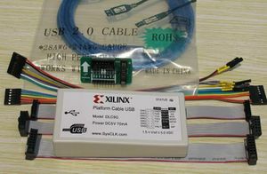
* Xilinx "Platform USB" programmer. | *Xilinx "Platform USB" programmer. A $25 Chinese clone is fine. | ||
: | :https://www.ebay.com/sch/i.html?_nkw=xilinx+usb&_sop=15 | ||
:Look for model DLC9G preferrably. DLC9LP next. DLC9 least. DLC10 is even newer and better and would work too, but is more expensive and not neccessary for this. | |||
:Get one that includes a "flying leads" cable. | |||
:Don't put "DLC9G" or "DLC9LP" in the search, you will only get the overpriced ones. Search "xilinx usb" and then look at the pictures, and pick one that shows DLC9G on the label and includes a flying leads cable. | |||
:[[File:DLC9G Clone.jpg|thumb]] | |||
: | |||
:Don't | |||
* | *PC with at least one usb port, and a COM port or usb-serial adapter. | ||
*Sandpaper, medium grit (120 or so) | *Sandpaper, medium grit (120 or so), and a flat surface like a cutting board. | ||
*[http://www.microcenter.com/product/391332/12_Watt_Miniature_Corded_Soldering_Iron Soldering Iron] | *[http://www.microcenter.com/product/391332/12_Watt_Miniature_Corded_Soldering_Iron Soldering Iron] | ||
:Do not necessarily need anything fancy. I actually used this exact one. | :Do not necessarily need anything fancy. I actually used this exact one to build a few REXs, although now I use a Hakko FX-888D. | ||
*[http://www.microcenter.com/product/448396/No-Clean_Flux_Core_Solder_Sn63-Pb37_-_2_Ounce_Spool Solder, fine pitch, 63/37, no-clean flux or rosin core] | *[http://www.microcenter.com/product/448396/No-Clean_Flux_Core_Solder_Sn63-Pb37_-_2_Ounce_Spool Solder, fine pitch, 63/37, no-clean flux or rosin core] | ||
| Line 58: | Line 35: | ||
*[http://www.microcenter.com/product/458849/Three_Lens_Multi-Magnifier Magnifying Glasses] | *[http://www.microcenter.com/product/458849/Three_Lens_Multi-Magnifier Magnifying Glasses] | ||
:Or the strongest reading glasses you can get at the local drug store. | :Or the strongest reading glasses you can get at the local drug store. 3.00x or more if you can find them. | ||
*[http://www.microcenter.com/product/451968/Technical_Grade_Isopropyl_Alcohol_999_-_32oz Alcohol for cleaning up] | *[http://www.microcenter.com/product/451968/Technical_Grade_Isopropyl_Alcohol_999_-_32oz Alcohol for cleaning up] | ||
| Line 65: | Line 42: | ||
*[http://www.microcenter.com/product/411268/Ultra_Fine_Point_Slanted_Tweezers__-_Black Tweezers] | *[http://www.microcenter.com/product/411268/Ultra_Fine_Point_Slanted_Tweezers__-_Black Tweezers] | ||
*[http:// | *[http://www.microcenter.com/product/426789/10_01_40_Single_Row_Headers Single-Row pin header] | ||
:You only need 10 pins. Break off a section of 6 pins, and a section of 4 pins. | |||
*A Tandy Model 100, 102, or 200. | |||
*A [[Model_100_102_200_600_Serial_Cable|9F-25M-Null-Modem Serial Cable]] | |||
=Prep the PCB= | |||
Lay a piece of medium grit (100-200) sandpaper face up on a hard flat surface like a cutting board. | |||
Sand the edges of the PCB on the sandpaper just enough to clean off the panelization break-away points. | |||
Use magnification to look closely at the castellated edge contacts for copper or gold "flags" hanging on the edge of most contacts. Scrape them off with and xacto knife. | |||
=Assembly= | =Assembly= | ||
==Electronic Components== | ==Electronic Components== | ||
Solder these parts onto the matching labeled locations on the pcb. | |||
:29F800 (on the back side) | :29F800 (on the back side) | ||
:XCR3064XL | :XCR3064XL | ||
:LP2980 | :LP2980 | ||
:R1 | :R1 = 10K ohm | ||
:C1 = 1.0 uF | |||
: | |||
Don't be afraid of those tiny legs on that TSOP-48 nand flash memory chip. Just use magnifying glasses, lots of flux, and the [https://youtu.be/erb6-i54tbo DRAG TECHNIQUE]. Another example: https://youtu.be/09qb0KY_IF4 | |||
Use a lot of flux, and little solder. | |||
Pay extreme attention to the flash chip. Use magnification to inspect those legs after soldering. Bridges are easy to get and hard to see on legs that small. | |||
==Clean== | |||
Even "No-Clean" flux should still be removed as much as possible after soldering. But without an ultrasonic cleaner, it is just about impossible to get the flux cleaned out from under the chips. So, using no-clean just means the flux that inevitably isn't removed, won't be too harmful. Use 99% isopropyl alcohol and a small paint brush to wash the flux off. | |||
==Carrier== | |||
Just snap the assembled pcb into the carrier. Place the end of the PCB without the big hole in the carrier first, then lower the other end down over the pin on the carrier. Flex the end of the carrier open a little and snap the PCB in. | |||
=Programming= | =Programming= | ||
==Program the CPLD | ==Program the CPLD== | ||
Now we need to flash the CPLD (Xilinx) with the '''.jed''' file. This configures the blank CPLD into a functional | Now we need to flash the CPLD (Xilinx) with the '''.jed''' file. This configures the blank CPLD into a functional circuit that actually does something. | ||
* | *Get the .jed file from [http://www.club100.org/memfiles/index.php?&direction=0&order=&directory=Steve%20Adolph/REX/info here]. | ||
* | *Install Xilinx "ISE 14.7 Lab Tools" | ||
: | :[https://drive.google.com/folderview?id=0Bys6eLbSbYyhVFBQSW1pclpjaWM Directions for Ubuntu Linux] | ||
* | *Connect the "platform usb" programmer to the 6-pin staggered row jtag header with a 1x6 single row male pin header. | ||
* | *Connect 5v and PORT_EN jumper to the 4-pin staggered row header in between TP1 & TP2 with a 1x4 single row male pin header. | ||
* | *Launch iMPACT | ||
: | :https://drive.google.com/open?id=1K7ySqfbmNTNUpB0WJCxkQRjMr9pZL4MRcM0e8tpEJhc | ||
* | *Program the .jed file. | ||
==Flash the Firmware== | ==Flash the Firmware== | ||
<!-- | <!-- | ||
Build 254 rf149.co has a bug in it's tpdd routines. | Build 254 rf149.co has a bug in it's tpdd routines. | ||
| Line 155: | Line 109: | ||
However, the T200 version of build 254 rf249.co, seems to be ok anyway. (it worked for me) | However, the T200 version of build 254 rf249.co, seems to be ok anyway. (it worked for me) | ||
--> | --> | ||
[http://bitchin100.com/wiki/index.php?title=REX_Release_4.9 4.9 update directions] | Follow the [http://bitchin100.com/wiki/index.php?title=REX_Release_4.9 4.9 update directions] to load the firmware. | ||
<!-- | <!-- | ||
| Line 161: | Line 115: | ||
--> | --> | ||
The directions for the 4.9 update state that you use any tpdd device to serve the 3 files to the M100/T102/T200, but in fact at least at present, it does not work with actual tpdd1 or tpdd2 drives at all, and is not reliable with any | The directions for the 4.9 update state that you use any tpdd device to serve the 3 files to the M100/T102/T200, but in fact at least at present, it does not work with actual tpdd1 or tpdd2 drives at all, and is not reliable with just any tpdd server either. You must use specifically [http://bitchin100.com/wiki/index.php?title=LaddieCon#LaddieAlpha LaddieAlpha]. | ||
TODO: Document this part better. This is a bullet list, but there are more details involved for each item to actually do | TODO: Document this part better. This is a bullet list, but there are more details involved for each item in order to actually do them. | ||
*Install any | *Get a proper [[Model_100_102_200_600_Serial_Cable|serial cable]] | ||
*Install any TPDD client on the M100/T102/T200: teeny, floppy, ts-dos. If you don't have anything already, then get the "dlplus" package and run the teeny installer that comes with it. | |||
*Get LaddieAlpha onto a | *Get LaddieAlpha onto a PC. | ||
*Get the 3 update files | *Get the 3 update files. | ||
*Use whatever | *Run LaddieAlpha in the dir with the 3 update files. | ||
*Use whatever TPDD client you installed on the M100 to copy rf149.co to the M100. | |||
*Run rf149.co on the M100. | *Run rf149.co on the M100. | ||
That was the last step. You're done! Consult the [http://bitchin100.com/wiki/index.php?title=Special%3ASearch&search=rex&fulltext=Search REX docs] to start using it! | |||
=References= | =References= | ||
| Line 180: | Line 135: | ||
[http://www.club100.org/memfiles/index.php?PHPSESSID=0iltg2un40287et7flm4m54387&direction=0&order=&directory=Steve%20Adolph Original sources and support files] | [http://www.club100.org/memfiles/index.php?PHPSESSID=0iltg2un40287et7flm4m54387&direction=0&order=&directory=Steve%20Adolph Original sources and support files] | ||
[https://oshpark.com/shared_projects/vFF7oXfw PCB] (This is now a dead link) | <!-- [https://oshpark.com/shared_projects/vFF7oXfw PCB] (This is now a dead link) --> | ||
[https:// | [https://drive.google.com/open?id=0Bys6eLbSbYyhV3NEdjhvWFlYMDg Copies of some of the sources and support files, and new sources for some things modified from the originals] | ||
[https://oshpark.com/shared_projects/5R4KDv8D Printed Circuit Board, pre-castellated] (this version is converted from the original EagleCAD 5 or lower .brd file, loaded in EagleCAD 6.6 and saved as new xml format EagleCad 6.x .brd file, then imported into KiCAD 4.07 pcbnew, then the edge cut lines edited, and saved as .kicad_pcb) | <!-- [https://oshpark.com/shared_projects/5R4KDv8D Printed Circuit Board, pre-castellated] (this version is converted from the original EagleCAD 5 or lower .brd file, loaded in EagleCAD 6.6 and saved as new xml format EagleCad 6.x .brd file, then imported into KiCAD 4.07 pcbnew, then the edge cut lines edited, and saved as .kicad_pcb) --> | ||
[https://github.com/aljex/REX1 pcb on github] | <!-- [https://github.com/aljex/REX1 pcb on github] --> | ||
Revision as of 11:51, 2 August 2019

Introduction
Building a REX, BKW version.
This is essentially a REX1 with a modified pcb layout from Steven Adolph's original.
Electronically identical.
Software identical.
PCB shaped to snap into a 3d-printed carrier, and provide connections for power and PORT_EN for programming the CPLD.
Parts & Materials
- If the flash memory chip is on backorder: How to Identify a Compatible Flash Chip from Elsewhere
Tools
- Xilinx "Platform USB" programmer. A $25 Chinese clone is fine.
- https://www.ebay.com/sch/i.html?_nkw=xilinx+usb&_sop=15
- Look for model DLC9G preferrably. DLC9LP next. DLC9 least. DLC10 is even newer and better and would work too, but is more expensive and not neccessary for this.
- Get one that includes a "flying leads" cable.
- Don't put "DLC9G" or "DLC9LP" in the search, you will only get the overpriced ones. Search "xilinx usb" and then look at the pictures, and pick one that shows DLC9G on the label and includes a flying leads cable.

- PC with at least one usb port, and a COM port or usb-serial adapter.
- Sandpaper, medium grit (120 or so), and a flat surface like a cutting board.
- Do not necessarily need anything fancy. I actually used this exact one to build a few REXs, although now I use a Hakko FX-888D.
- Or the strongest reading glasses you can get at the local drug store. 3.00x or more if you can find them.
- Don't really need this. The "no-clean" flux above can be left on, or cleaned with warm water.
- You only need 10 pins. Break off a section of 6 pins, and a section of 4 pins.
- A Tandy Model 100, 102, or 200.
Prep the PCB
Lay a piece of medium grit (100-200) sandpaper face up on a hard flat surface like a cutting board.
Sand the edges of the PCB on the sandpaper just enough to clean off the panelization break-away points.
Use magnification to look closely at the castellated edge contacts for copper or gold "flags" hanging on the edge of most contacts. Scrape them off with and xacto knife.
Assembly
Electronic Components
Solder these parts onto the matching labeled locations on the pcb.
- 29F800 (on the back side)
- XCR3064XL
- LP2980
- R1 = 10K ohm
- C1 = 1.0 uF
Don't be afraid of those tiny legs on that TSOP-48 nand flash memory chip. Just use magnifying glasses, lots of flux, and the DRAG TECHNIQUE. Another example: https://youtu.be/09qb0KY_IF4 Use a lot of flux, and little solder.
Pay extreme attention to the flash chip. Use magnification to inspect those legs after soldering. Bridges are easy to get and hard to see on legs that small.
Clean
Even "No-Clean" flux should still be removed as much as possible after soldering. But without an ultrasonic cleaner, it is just about impossible to get the flux cleaned out from under the chips. So, using no-clean just means the flux that inevitably isn't removed, won't be too harmful. Use 99% isopropyl alcohol and a small paint brush to wash the flux off.
Carrier
Just snap the assembled pcb into the carrier. Place the end of the PCB without the big hole in the carrier first, then lower the other end down over the pin on the carrier. Flex the end of the carrier open a little and snap the PCB in.
Programming
Program the CPLD
Now we need to flash the CPLD (Xilinx) with the .jed file. This configures the blank CPLD into a functional circuit that actually does something.
- Get the .jed file from here.
- Install Xilinx "ISE 14.7 Lab Tools"
- Connect the "platform usb" programmer to the 6-pin staggered row jtag header with a 1x6 single row male pin header.
- Connect 5v and PORT_EN jumper to the 4-pin staggered row header in between TP1 & TP2 with a 1x4 single row male pin header.
- Launch iMPACT
- Program the .jed file.
Flash the Firmware
Follow the 4.9 update directions to load the firmware.
The directions for the 4.9 update state that you use any tpdd device to serve the 3 files to the M100/T102/T200, but in fact at least at present, it does not work with actual tpdd1 or tpdd2 drives at all, and is not reliable with just any tpdd server either. You must use specifically LaddieAlpha.
TODO: Document this part better. This is a bullet list, but there are more details involved for each item in order to actually do them.
- Get a proper serial cable
- Install any TPDD client on the M100/T102/T200: teeny, floppy, ts-dos. If you don't have anything already, then get the "dlplus" package and run the teeny installer that comes with it.
- Get LaddieAlpha onto a PC.
- Get the 3 update files.
- Run LaddieAlpha in the dir with the 3 update files.
- Use whatever TPDD client you installed on the M100 to copy rf149.co to the M100.
- Run rf149.co on the M100.
That was the last step. You're done! Consult the REX docs to start using it!
References
Original sources and support files