Building a REX

Introduction
Building Steven Adolf's REX from scratch.
Brian K. White - bw.aljex@gmail.com
Parts/Materials
Bill of Materials. Order each of these.
These are parts to build 3 REX boards, because you will get 3 boards from OSHPark. If you only want to build one or two boards, reduce the quantities of the parts from DigiKey before checking out.
- ONE of these: PCB OR Pre-castellated PCB
- If the flash memory chip is on backorder: How to Identify a Compatible Flash Chip from Elsewhere
- Card stock, such as from a cereal box. 2 pieces 1/2" x 1-1/2" per REX.
Tools
- Xilinx "Platform USB" programmer.
- I used this actual ebay item: http://ebay.com/itm/112073269777
- But ebay links die after a while, so if/when the link above is dead, just search for "Xilinx Platform USB" on ebay or amazon etc.
- There are a lot of overpriced programmers, and I include the official Xilinx ones in that group. There is no reason I can see why a jtag programmer should cost $200.
- So, go on ebay and search exactly "xilinx usb", then sort by "price+shipping, lowest first, and filter by buy-it-now.
- Then skip the cables and adapters until you get to the actual programmers. You want one of the kits that has the programmer and several adapter cables, all for about $25.
- Then expand the item pictures and verify that it says DLC9G or DLC9LP, or DLC9. Prefer DLC9G most, then DLC9LP. DLC9 is oldest but would still work fine for this. DLC10 probably works too, if you feel like spending the money.
- Don't search for DLC9G or DLC9LP directly by name, you will only get the overpriced ones. Search "xilinx usb" and then look at the pics.
- "Modern" PC with at least one usb port, and a COM port or usb-serial adapter.
- To run the Xilinx software to program the CPLD, and to run a TPDD server to complete the programming process, and to get software onto the M100.
- "Modern", only in comparison to the Model 100. I used a 12 year old atom-powered netbook, running Ubuntu 16.04. The point is it is possible to do the entire job with very little special requirements, IE even a dirt cheap netbook running only free software and OS is enough. It did require several gigs of hard drive space for the Xilinx software though, and getting the LabTools software installed and working, and getting the special usb drivers working DID require some non-trivial futzing around. But I described all that [Here] if you want to use Linux. (TODO: Windows directions, MAC directions)
- Sandpaper, medium grit (120 or so)
- This is just to clean up and smooth the edges of the PCB a little.
- Do not necessarily need anything fancy. I actually used this exact one.
- Or the strongest reading glasses you can get at the local drug store.
- Don't really need this. The "no-clean" flux above can be left on, or cleaned with warm water.
- Test Hook to jump between the jtag vcc pin and PORT_EN (R3) to program the CPLD.
- Just need a little section of 6 pins snapped off of one stick. The rest are not needed, but you almost can't buy them in any smaller quantity.
- A Model 100, 102, or 200.
Assembly
Electronic Components
Install these parts:
- 29F800 (on the back side)
- XCR3064XL
- LP2980
- R1 = 0 ohm
- R3 = 10K ohm
- C4 = 1.0 uF
All other locations left empty.
Orientation of the chips:


How to solder the chips without special tools: DRAG TECHNIQUE , another example: https://youtu.be/09qb0KY_IF4
Pay extreme attention to the flash chip on the back. Use magnification to inspect those legs after soldering. Bridges are very easy to get and very hard to see on legs that small.
Spacer & Extractor
- 1/2" double sided tape
- Cereal box
- Cloth Ribbon, 3/8" to 9/16" width.
Cut a length of ribbon about 2 1/2" long, and melt the cut edges with the soldering pen to keep them from fraying.
Apply double sided tape to bottom of REX (The side with the flash chip, not the Xilinx).
Stick the ribbon to the tape on the REX, in the center of the ribbon, aligned lengthwise.
Add another piece of double sided tape on top of the ribbon, only as long as the REX is.
Cut a piece of cereal box about 1/2" x 1-1/4", and stick that to the tape, aligned lengthwise, centered on the REX.
Programming
Program the CPLD with the .jed
Now we need to flash the CPLD (Xilinx) with the .jed file. This configures the blank CPLD into a functional device or circuit that actually does something.
- Get the .jed file from here.
- Install LabTools 14.7 from Xilinx
- Supply +5vdc to pin 1 of the board edge, and gnd to pin 14.
- The simplest way to do this is just pop the REX into a Model 100 (or 102, or 200) with new batteries or a wall plug, turn it on, go into BASIC and issue a "POWER CONT" command (tells the M100 not to turn itself off when idle). The ram in the M100 would probably get scrambled along the way, so back up any files you want on the M100 first.
- Another option is take any 5v phone charger, cut off the usb plug, cut off 3 inches of the outer insulation so you have 2 separate wires, strip 1/4" of insulation off of those, and use rubber bands wrapped around the REX to hold the red wire on pin 1, and black or bare on pin 14.
- (TODO indicate where pin 1 and 14 are)
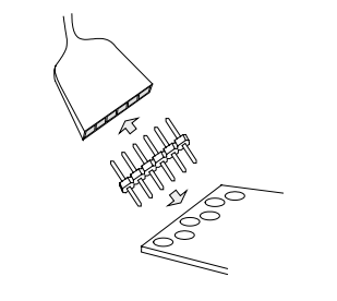
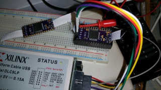
- Hook up the "platform usb" programmer to the jtag pins with a single row male-male double-sided pin header.
- The staggered offset of the holes, while the pins in the header are in a straight line, creates the tension so the pin header stays in place and all pins make good electrical contact without needing an actual socket. It takes some wiggling to get the pins inserted, but that is how it works.
- The LED on the usb programmer should turn green, indicating that the programmer is detecting the correct/expected 3.3vdc on the board.


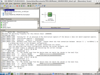
- Get the iMPACT program up and running.
- FILL IN - what menu items to click on to load the .jed file, something like "Assign Configuration something..." also "verify chain" ?
- Temporarily pull PORT_EN high on the CPLD (the Xilinx chip) by jumping from the jtag vcc pin (labeled 3V3), to R3, on the side of R3 closer to the Xilinx chip. (Be careful to get this right! The other side of R3 is GND. If you short vcc to gnd you may burn out the LP2980 3.3vdc regulator on the REX.) Lift the programmer vcc wire slightly up the jtag vcc pin, and clip a J-hook test/jumper lead to the jtag vcc pin. Then manually hold the other end of the jumper lead to touch the side of R3, and hold it there carefully.


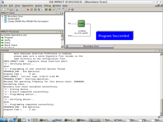
- While holding the PORT_EN jumper in place, use iMPACT to program the .jed file.
- FILL IN - what actual menu options / steps?


Flash the Firmware
The firmware gets written to the flash memory. This includes an option-rom image loaded in one of the 32k blocks of flash, which in turn contains REXMGR.
To do this, follow the directions for the 4.9 update. The "update" also works for first-time install.
The directions for the 4.9 update state that you use any tpdd device to serve the 3 files to the M100/T102/T200, but in fact at least at present, it does not work with actual tpdd1 or tpdd2 drives at all, and is not reliable with any other tpdd server/emulator either, except LaddieAlpha.
TODO: Document this part better. This is a bullet list, but there are more details involved for each item to actually do it.
- Install any dos on the M100/T102/T200: teeny, floppy, ts-dos.
- This will generally require a special serial cable.
- Get LaddieAlpha onto a modern host machine.
- Get the 3 update files, and share them with LaddieAlpha.
- Use whatever dos you installed on the M100 to copy rf149.co to the M100.
- Run rf149.co on the M100.
This was the last step. You're done! Consult the REX docs to start using it!
References
Original sources and support files
PCB (This is now a dead link)
Copies of some of the sources and support files, and new sources for modified from the originals
PCB (This version is probably good, although it's a salvaged earlier version of the rex.brd file that has messier silk screen)
Printed Circuit Board, pre-castellated (this version is converted from the original EagleCAD 5 or lower .brd file, loaded in EagleCAD 6.6 and saved as new xml format EagleCad 6.x .brd file, then imported into KiCAD 4.07 pcbnew, then the edge cut lines edited, and saved as .kicad_pcb)