Disk/Video Interface: Difference between revisions
Jump to navigation
Jump to search
| Line 10: | Line 10: | ||
==Cable== | ==Cable== | ||
===For Model 100 | ===For Model 100=== | ||
(This is still pending verification) | (This is still pending verification) | ||
| Line 23: | Line 23: | ||
* Crimp the cable in the dip connector such that if you are looking at the dip connector with the #1 pin top-left and pins pointing away from you, the cable exits to the right, red stripe on top. | * Crimp the cable in the dip connector such that if you are looking at the dip connector with the #1 pin top-left and pins pointing away from you, the cable exits to the right, red stripe on top. | ||
* Arrange the cable on the 40 pin female idc connector such that the red stripe goes to the pin one marker, and the cut end of the cable ends on the side of the connector with the polarity notch, and the cable extends away from the connector on the side opposite the polarity notch. Crimp the cable. Then fold the cable back over the top to snap on the strain relief clip. Now the cable is going the same direction as the key notch. | * Arrange the cable on the 40 pin female idc connector such that the red stripe goes to the pin one marker, and the cut end of the cable ends on the side of the connector with the polarity notch, and the cable extends away from the connector on the side opposite the polarity notch. Crimp the cable. Then fold the cable back over the top to snap on the strain relief clip. Now the cable is going the same direction as the key notch. | ||
Some DIP IDC connectors connect pin 1 to conductor 1, and pin 40 to conductor 2<br> | |||
While some others connect pin 1 to conductor 2, and pin 40 to conductore 1 | |||
So, you may need to swap the positions of every other wire, the same as for Model 102 below, depending on which type of DIP connector you happen to have. I will fill in more definitive info about this when I have actual connectors and cables in my hands to test and document from actual observation. | |||
===For Model 102=== | ===For Model 102=== | ||
Revision as of 23:38, 17 October 2017


Manuals
Boot Disk
Boot Disk files from Steven Adolf on Club100
Cable
For Model 100
(This is still pending verification)
Parts:
- 40pin DIP idc connector
- 40pin female idc connector, with polarity notch and strain-relief
- 40pin ribbon cable, 20 inches
Assembly:
- Crimp the cable in the dip connector such that if you are looking at the dip connector with the #1 pin top-left and pins pointing away from you, the cable exits to the right, red stripe on top.
- Arrange the cable on the 40 pin female idc connector such that the red stripe goes to the pin one marker, and the cut end of the cable ends on the side of the connector with the polarity notch, and the cable extends away from the connector on the side opposite the polarity notch. Crimp the cable. Then fold the cable back over the top to snap on the strain relief clip. Now the cable is going the same direction as the key notch.
Some DIP IDC connectors connect pin 1 to conductor 1, and pin 40 to conductor 2
While some others connect pin 1 to conductor 2, and pin 40 to conductore 1
So, you may need to swap the positions of every other wire, the same as for Model 102 below, depending on which type of DIP connector you happen to have. I will fill in more definitive info about this when I have actual connectors and cables in my hands to test and document from actual observation.
For Model 102
Parts:
- 40pin male idc connector, with polarity notch
- 40pin female idc connector, with polarity notch and strain-relief
- 40pin ribbon cable, 20 inches
Assembly:
- Crimp the male connector to one end of the cable with the cut end of the cable ending on the key-notched side of the connactor, and the red stripe toward the pin 1 marker. The cable extends away from the connector on the side opposite the key notch.
- Arrange the other end of the cable and female connector the same as above, except also:
- Peel the conductors apart into 20 pairs, one inch long.
- Flip each pair over before putting onto the connector.
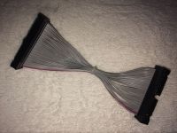
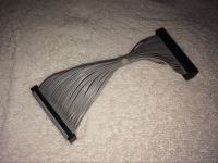
Finished example:
- These pics are from an ebay ad.
- You probably want to make the cable longer than this.
- Or, maybe make it even shorter than this and use just use it as an adapter, and use a generic 40 pin extension cable for whatever length you want.