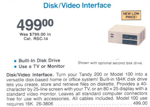
Disk/Video Interface: Difference between revisions
| Line 44: | Line 44: | ||
:http://ebay.com/itm/182240437070 | :http://ebay.com/itm/182240437070 | ||
====Work in progress | ====Work in progress==== | ||
Facebook group member Ted Saari provides the following: | Facebook group member Ted Saari provides the following: | ||
Revision as of 20:58, 26 October 2017
Manuals
Boot Disk
Boot Disk files from Steven Adolf on Club100
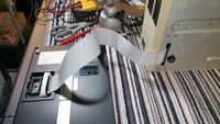
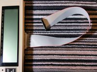
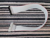
Cable
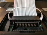
For Model 100
(This is still pending verification, see "Work in progress..." below)
Parts:
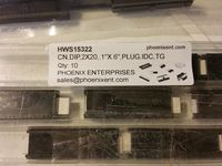
- 40pin DIP idc connector
- 40pin female idc connector, with polarity notch and strain-relief
- 40pin ribbon cable, 20 inches
Assembly:
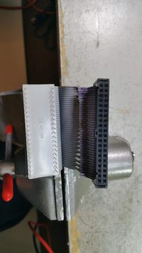
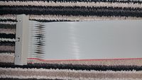
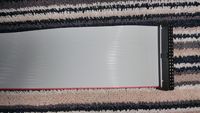
- Crimp the cable in the DIP connector such that if you are looking at the dip connector with the #1 pin top-left and pins pointing away from you, the cable exits to the right, red stripe on top.
- Crimp the female IDC connector on the other end of the cable. Make sure the red wire goes to the Pin-1 mark on the connector.
NOTE
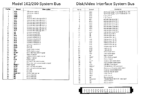
Some DIP IDC connectors connect pin 1 to conductor 1, and pin 40 to conductor 2
While some others connect pin 1 to conductor 2, and pin 40 to conductor 1.
So, you may, or may not, need to swap the positions of every other wire, the same as for Model 102 below, depending on which type of DIP connector you happen to have.
The DIP IDC connector linked above connects pin 1 to conductor 2, and does NOT need to have the conductors split into pairs and swapped. With connector linked above, you only have to crimp the cable normally.
The cirmp-on dip40 connectors are uncommon these days, and hard to search for. So here are some more sources.
Work in progress
Facebook group member Ted Saari provides the following:
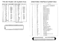
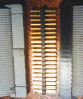
- 1-20 on the DIP connect to 1-39 on the left side of the IDC.
- 21-40 on the DIP connect to 40-2 on the right side of the IDC.
- Basically the left row on the DIP match to the left row on the IDC and the same for the right side, as viewed from this picture.
For Model 102 and 200
Parts:
- 40pin male idc connector, with polarity notch
- 40pin female idc connector, with polarity notch and strain-relief
- 40pin ribbon cable, 20 inches
Assembly:
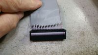
- Crimp the female connector on one end of the cable. Make sure the red wire goes on the Pin-1 marker on the connector.
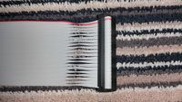
- On the other end of the cable, peel apart the conductors into 20 pairs, about 2 to 3 inches long.
- Take an extra female connector with strain relief clip and snap it all together without any cable. The strain relief clip on this connector forms a slot that is exactly the right size to hold the cable.
- Take the first wire pair, with one red wire, flip it over and put it into the loose connector strain relief. Repeat for the remaining 19 pairs. In the end you should have all 40 wires in the slot, each pair flipped over on one side of the connector, and the wires all flat and lined up like a single cable on the other side or the connector.
- Crimp the male connector on these wires. Make sure the Pin 1 mark on the connector is on the red wire side of the cable.
- Pry apart the clips on the makeshift cable guide, or just break it off.
Quick-n-Dirty neat trick
Another much easier way to get the wires crossed the right way, is just join 2 ordinary female idc connectors with a straight through double ended male-male idc pin header. The arrangement of the female connectors matters. More explicit and definitive info about that will be added later. Thanks Mike Stein for this trick.
Wonderful Hacks from Days Gone By
Use the cassette motor control to use both sides of a double-sided drive!
