TPDD
Overview
There were two versions of the Tandy Portable Disk Drive. Both were very similar. The drive is a a re-branded Brother FB-100.
Common features of both versions
- Size, shape, weight
- Batteris: 4 x AA
- Wall power: 5.5mm x 2.1mm, 6vdc, center negative, 400ma (Tandy 26-3804)
- Media: 3.5" DD, aka "720K" diskettes (not HD 1.44M)
- Drive is single-sided. The disks may be single or double-sided, but the drive only uses one side.
Tandy Portable Disk Drive
100K
Tandy Portable Disk Drive 2
200K in the form of 2 100K banks (still only uses one side of the disk)
Parts
Belt
Standard size code: FRW-8.5
Search "FRW 8.5 belt" on Google or ebay
Cable
The "RS-232" interface to the TPDD is actually 0v to -5v TTL, while rs232 serial ports use -12v to +12v. So the cable isn't just a cable, it has electronics to convert the signal levels.
Pinout
+------------------------------------------------+
|                                                |
|                                                |
|                 RS-232C                        |
|                   ___                          |
|               +--+   +--+              +-----+ |
|               | 7 5 3 1 |              | (o) | |
|               | 8 6 4 2 |              |     | |
|               +---------+              +-----+ |
+------------------------------------------------+
- 1 GND
- 2 CTS
- 3 DTR
- 4 RTS
- 5 DSR
- 6 TXD
- 7 RXD
- 8 NC
In the beginning, there was the Marty Goodman Document, and it was good.
More recently, Rick Shear has taken a new and very careful look at a real cable, and the Marty Goodman doc, and has probably identified the "mystery" components that Marty Goodman talks about. It looks right, and this cable does indeed work.
To build a cable based on Rick's pcb, but using all standard parts that you can buy instead of having to find a FB100 cable and destroy it to get the special plug for the TPDD:
- The numbers 1-7 on the PCB correspond to the numbers on the TPDD connector in the diagram above. Pin 8 on the TPDD is not used.
- You need a special crimp tool to crimp 28awg dupont style pins. Example: SN-28B Crimp Tool.
- Additional materials:
- 3/16" heat shrink tubing
- 1/2" heat shrink tubing (double wall, 3:1 ratio)
- The pins on the db25 connector above will be too long for the solder pads on the pcb. You will need to cut them appoximately in half. Rick used a connector with solder cups instead of through-hole pins, because the solder cup style is what typically comes with typical back shells. But a standard 1.6mm thick pcb doesn't actually fit in betwen the rows of solder cups.
- The back shell is special. Most back shells don't fit in the opening in a Model 100. The back shell in the digikey cart above does.
Cable BKW 1
Same as above, but the pcb is smaller to allow more room inside the back shell for strain-relief, and the db25 solder pads are longer to fit the pins without cutting.
Same components, materials, tools as above
Cable BKW 1
Re-work of Rick's pcb:
- smaller pcb to allow more room to strain-relieve the cable end inside the back shell, and allow possible compatbility with more types of backshells.
- fewer, shorter, simpler traces and vias
- adjusted footprint for db25 plug to use a through-hole solder type instead of solder cup type, so the pcb actually fits between the pins. That type has longer pins so the solder pads needed to be lengthened.
Cable BKW 2
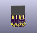
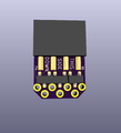
New design with the transistors on the TPDD-end instead of the DB25-end. This way you do not need to crimp Dupont style pins. You just assemble this tiny pcb, cut the 9-pin plug off of a cheap pre-made 9/25 modem cable and throw it away, and solder the cable with factory molded 25 pin plug to this pcb, and finally secure with some hot-glue & heat-shrink, maybe a zip-tie. This uses the same transistor as the two other versions above. Still working on an answer for polarity. Probably replace the single 2x4 header with a 2x3 header standing up, and two 1x2 headers to either side of that.
Cable BKW 3
The through holes for the wires were way too small and close in BKW2.
Cable BKW 4
Adds a place to secure the cable with a zip tie.
- PCB: https://oshpark.com/shared_projects/dyMZxoye
- BOM: https://www.digikey.com/short/pbc3pp
- Assembly:
- Solder all components to pcb per the render pics.
- Cut the db9 plug off the serial cable. Strip the outer sheath back 1 to 2 inches. Strip each wire 1/8".
- Put 2 to 3 inches of 1/2" diameter heat shrink on the serial cable. (don't shrink yet)
- Use a dmm continuity tester to identify which wires go to which pins on the db25. Find pin 2 on the db25, find which wire goes to pin 2, solder that wire to through-hole labeled 2 on the pcb. Repeat for all the numbered holes. Cut any left-over wires short at the cable sheath.
- Secure the end of the cable to the pcb with a zip-tie.
- Add some hot-glue around the soldered wires where they meet the pcb.
- Pull the two un-soldered pins from the back of the female 2x3 pin socket. Or cut them off with flush cutters.
- Slide the heat-shrink up over the pcb and shrink.
Software
For PCs
TPDD used double density 3.5" disks, but used a format that is incompatible with modern pc drive controllers. Normal MS-DOS formatted disks are written with MFM encoding, while the TPDD used FM encoding. Even using special software to read non-standard formats, you can't make a normal drive & drive controller read or write FM.
To read or write a TPDD disk from a modern machine, you need a working TPDD drive and the special RS232-to-TTL level-shifting serial cable that came with it, and a "TPDD Client" software to talk to the drive over the serial connection the same way the M100 does.
There are several TPDD clients for more modern machines. Most of these are themselves also no longer modern. For example Lap-Desk and PDD are both 16-bit DOS programs that don't work on Windows.
TpddTool Python TPDD Client
For M100/102/200
The normal way to use a TPDD is to install a "dos" on an M100. Several such dos's have been made. The drive came with a utility disk and a functional dos called "floppy". Others have been made by 3rd parties that provided more features or smaller ram footprint or more flexible installation/usage. There are also various special purpose utility programs aside from dos's.


