Building a REX: Difference between revisions
(→Tools) |
No edit summary |
||
| (255 intermediate revisions by 2 users not shown) | |||
| Line 1: | Line 1: | ||
[[File: | [[File:20190730 232012.jpg|800px]] | ||
<gallery> | |||
REX_Classic_bkw_1.png | |||
REX_Classic_bkw_2.png | |||
REX_Classic_bkw_3.png | |||
REX_Classic_bkw_4.png | |||
REX_Classic_bkw_5.png | |||
REX_Classic_bkw_6.png | |||
REX_Classic_bkw_7.png | |||
REX_BKW_C11_8.jpg | |||
REX_BKW_C11_9.jpg | |||
REX_BKW_C11_10.jpg | |||
</gallery> | |||
<!-- | |||
rex-bkw-c8-10.jpg | |||
rex-bkw-c8-9.jpg | |||
rex-bkw-c8-6.jpg | |||
rex-bkw-c8-7.jpg | |||
--> | |||
=Introduction= | |||
Building a REX<br> | |||
This is a version of [http://bitchin100.com/wiki/index.php?title=REXclassic Steven Adolph's REX Classic] with a modified PCB design.<br> | |||
It is electrically identical to REX Classic, and uses the REX Classic firmware & software.<br> | |||
[ | |||
The PCB layout and shape are modified to: | |||
* snap into a 3d-printed carrier to fit the Molex78805 socket | |||
* provide connections for power and PORT_EN for programming the CPLD | |||
'''[[REX:Build_(original_version)|Original version of this page, for building the original REX1]]''' | |||
[https://github.com/bkw777/REX_Classic PCB Source]<br> | |||
: | [https://github.com/bkw777/Molex78802_Module Carrier Source] | ||
* [https://www. | =Parts & Materials= | ||
: | <!-- ==For Tandy 100/102/200== --> | ||
* PCB: [https://oshpark.com/shared_projects/2aTIo5Fq OSHPark] or [https://www.pcbway.com/project/shareproject/REX_Classic__BKW_re_spin.html PCBWAY] | |||
* BOM: [https://www.digikey.com/short/tj7bzf3h Digi-Key] | |||
: | * Carrier: [http://shpws.me/SGNn Shapeways] or [https://www.sculpteo.com/en/print/molex78802_pcb_28-13/Bw4x3yG6 Sculpteo] | ||
: | |||
Note if ordering from PCBWAY: On the order page, you may have to manually change "Min tracks/spaces" to "6/6mil"<br> | |||
All tracks & spaces are well over 6 mil (everything is 0.2mm which is almost 8 mil), and that setting drops the price from $50 to $5 | |||
: | |||
ENIG adds a lot of cost on PCBWAY and JLCPCB lately.<br> | |||
Currently the cheapest way to get an ENIG version for gold contacts (other than OSHPark) is [https://www.elecrow.com/ Elecrow].<br> | |||
Upload the gerber zip from the [https://github.com/bkw777/REX_Classic/releases/latest releases], and manually select ENIG and Castellated Holes, and just use the cheapest shipping. | |||
: | |||
<!-- | |||
The github includes a working re-spin REX Classic for NEC. | |||
REX NEC requires a different .jed file for the cpld, which is not publicly available. | |||
However, if you have a REX NEC, you can dump a .jed file from it, and use that to program new REX NECs. | |||
--> | |||
<!-- | |||
==For NEC PC-8201/8300== | |||
* PCB: (see github) | |||
* BOM: Same as above, but add 50 of these legs (you need 28, but 50 costs less than 28): https://www.digikey.com/product-detail/en/te-connectivity-amp-connectors/1544210-2/A117856CT-ND/4729775 Or these: https://www.digikey.com/en/products/detail/mill-max-manufacturing-corp/3121-2-00-15-00-00-08-0/436677 | |||
* No carrier needed. | |||
--> | |||
[[REX:flash|Other Compatible Flash Chips and how to identify them]] | |||
=Tools= | |||
[[File:DLC9G Clone.jpg|thumb]] | |||
*[https://www.ebay.com/sch/i.html?_nkw=xilinx+usb&_sop=15 Xilinx Platform USB programmer] | |||
:Cheap Chinese clone is fine. | |||
:Look at the pictures for ones that say model DLC9G, or DLC9LP. Don't put "DLC9G" or "DLC9LP" in the search, you will only get the overpriced ones. | |||
:Get one that includes a "flying leads" cable, with separate loose individual wires on one end.<br clear=all> | |||
[[File:Usb-ttl-cable.jpg|thumb]] | |||
*[https://www.ebay.com/sch/i.html?_nkw=usb+ttl+cable&_sop=15 5v power source with dupont sockets] | |||
: | :A cheap usb-ttl cable is perfect. It's cheap, and already ends in loose wires with female dupont pins. | ||
: | :Just use the red and black wires and ignore the rest.<br clear=all> | ||
* | *PC with at least one usb port, and a COM port or usb-serial adapter. | ||
* | *Sandpaper, medium grit (120 or so), and a hard flat surface like a cutting board. | ||
* http://www.microcenter.com/product/ | *[http://www.microcenter.com/product/391332/12_Watt_Miniature_Corded_Soldering_Iron Soldering Iron] | ||
: | :Do not necessarily need anything fancy. I actually used this exact one to build a few REXs, although now I use a Hakko FX-888D with a T18-C2 tip. | ||
* http://www.microcenter.com/product/ | *[http://www.microcenter.com/product/448396/No-Clean_Flux_Core_Solder_Sn63-Pb37_-_2_Ounce_Spool Solder, fine pitch, 63/37, no-clean flux] | ||
* http://www.microcenter.com/product/ | *[http://www.microcenter.com/product/444655/SRA_No-Clean_312_Flux_Pens No-Clean Flux] | ||
*[http://www.microcenter.com/product/436735/PV_Jr_Mini_Vise Mini Vise] | |||
*[http://www.microcenter.com/product/458849/Three_Lens_Multi-Magnifier Magnifying Glasses] | |||
:Or the strongest reading glasses you can get at a local drug store. 3.00x or higher. | |||
*[http://www.microcenter.com/product/451968/Technical_Grade_Isopropyl_Alcohol_999_-_32oz 99.9% Isopropyl Alcohol] | |||
*[http://www.microcenter.com/product/411268/Ultra_Fine_Point_Slanted_Tweezers__-_Black Tweezers] | |||
[[File:1x6 1x4 shunt.jpg|thumb]] | |||
*[https://www.digikey.com/short/pb0wvj Pin Headers and Shunt] | |||
:0.1" (2.54mm) pitch single row male pin header | |||
:1x6 | |||
:1x4 | |||
:one shunt | |||
<br clear=all> | |||
* | *A Tandy Model 100, 102, or 200. | ||
* | *A [[Model_100_102_200_600_Serial_Cable|9F-25M-Null-Modem Serial Cable]] | ||
* | *Optional but recommended: [https://www.amazon.com/dp/B072JXQ9P5/ Ultrasonic Cleaner] and [https://www.sra-solder.com/sra-trupower-35-circuit-board-ultrasonic-cleaning-solution-1-quart saponifying PCB cleaning solution] and distilled or deionized water. | ||
* | =Software= | ||
: | *Xilinx ISE 14.7 Lab Tools | ||
:Lab Tools is a subset of ISE. You can use either ISE or Lab Tools, but you only need Lab Tools to program the REX. | |||
:This software is old and needs special futzing to make it work, no matter what OS you are using. | |||
:[https://drive.google.com/folderview?id=0Bys6eLbSbYyhVFBQSW1pclpjaWM Installing on Ubuntu Linux] | |||
:[https://www.micro-nova.com/xilinx-ise-win10 Installing on Windows]. | |||
*A [[TPDD_client]] to run on the M100 | |||
:There are several tpdd clients, and several ways to get one installed. These are a few options: | |||
::For Mac, Linux, FreeBSD, any other unix: Get [http://gitlab.com/bkw777/dl2 dl2] and use the bootstrap option to install TEENY.100 or any of the other options listed by "$ dl -l" | |||
::For Windows: Get [http://gitlab.com/bkw777/tsend tsend.ps1] and use it to install TEENY.100 or any of the clients found at https://github.com/bkw777/dl2/tree/master/clients | |||
::Play [[File:DOS100.CO.MP3]] into the cassette port to install TS-DOS. (SOUND OFF:CLEAR 0,57089:RUNM "CAS:DOS100.CO") | |||
::Get a real tpdd and bootstrap it's utility disk to install "Floppy". | |||
* | *A [[TPDD_server]] to run on a modern host machine | ||
:For Mac, Linux, FreeBSD, any unix: [http://gitlab.com/bkw777/dl2 dl2] | |||
:For Windows: [http://bitchin100.com/wiki/index.php?title=LaddieCon#LaddieAlpha LaddieAlpha] | |||
<!-- | |||
This is all still true, but most people will not have any problem. It depends on how slow the host machine is, and most are fast enough. | |||
So it's not worth cluttering up and complicating the directions which are already complicated enough. | |||
The bug is definitely in the RF#49.CO util rather than in the other tpdd emulators, because for one thing, RF*49.CO does not work with an *actual TPDD drive*. | |||
This also only started with build 254. Build 162 works fine. | |||
*[http://bitchin100.com/wiki/index.php?title=LaddieCon#LaddieAlpha LaddieAlpha] | |||
:The rex firmware updater needs a TPDD server. | |||
:dl2 and mComm above are both tpdd servers, which come with tpdd client installers, and previously you used to be able to just use one of those packages for everything. | |||
:But there is a bug in the latest REX build 254 files, such that it only works (reliably) with LaddieAlpha as the TPDD server. | |||
:But LaddieAlpha does not come with any dos installer. | |||
:So, right now it's a bit inconvenient. You have to get one of the above packages just to use it's dos installer, and then you have to get LaddieAlpha also, and use it for the rest of the rex setup process. | |||
--> | |||
* | *[http://www.club100.org/memfiles/index.php?action=downloadfile&filename=rex_0110_April24%202011_no%20RST.jed&directory=Steve%20Adolph/REX/info& REX1 CPLD Jedec file] | ||
= | *[http://bitchin100.com/wiki/index.php?title=REX REX1 firmware] | ||
:Start there, and follow the links to whatever is the latest "REX Release x.x Rebuild Package" zip file. | |||
=== | =Procedure= | ||
==Prep the Bare PCB== | |||
Lay a piece of medium grit (100-200) sandpaper face up on a hard flat surface like a cutting board. | |||
Sand the edges of the PCB on the sandpaper just enough to clean off the panelization break-away points. | |||
[[File:Castellation flags.jpg|thumb]] | |||
Use magnification to look closely at the castellated edge contacts for copper or gold "flags" hanging on the edge of most contacts. Scrape them off with an xacto knife.<br clear=all> | |||
==Solder the Electronic Components== | |||
[[File:Soldered top.jpg|thumb]] | |||
[[File:Soldered bottom.jpg|thumb]] | |||
Solder these parts onto the matching labeled locations on the pcb. | |||
=== | :U1 = XCR3064XL | ||
: | :U2 = 29F800 | ||
: | :U3 = LP2980-3.3 | ||
: | :R1 = 10K | ||
:C1 = 1uF | |||
:TP1 & TP2 = right-angle pin (optional) | |||
Don't be too intimidated by the tiny legs on that TSOP-48 chip.<br> | |||
Just use magnifying glasses, lots of flux, and the [https://youtu.be/erb6-i54tbo DRAG TECHNIQUE].<br> | |||
Another example: https://youtu.be/09qb0KY_IF4 | |||
Cut a | The TP1 and TP2 pins are only needed if you think you will ever perform the hardware modification required to use the [http://bitchin100.com/wiki/index.php?title=Main_ROM_Management_Feature main rom management feature]. See [[FlexROM_100]] or [[FlexROM_102]] to facilitate this. | ||
<br clear=all> | |||
<!-- | |||
===NEC=== | |||
For the NEC version, do the DIP legs the same way as [[FlexROM_100]]. | |||
:Cut 2 strips of 14 pins each | |||
:Cut the top (larger end) off of all the pins using ordinary scissors, leaving a simple "comb" of pins. | |||
:Insert the "comb" into the top of the pcb and poke the legs down through about 1/2 way. The frame holding all the pins together should be on the top side of the pcb, 2-3mm above the pcb. The legs sticking out the bottom of the pcb should be 4 to 6 mm long. | |||
:Adjust the leg on one end of the row and solder that leg. | |||
:Adjust the leg on the opposite end of the row so the row is even, and solder that leg. | |||
:Solder all remaining legs. | |||
:Examine the legs for excess solder on the bottom of the pcb and along the length of the legs. If there is any solder built up on the legs, use flux and solder wick to remove it. | |||
:When you are sure the legs are all good, use flush cutters and cut the top of each leg off flush with the top of the pcb. | |||
[[File:FlexROM_100-12.jpg|thumb]] | |||
<br clear=all> | |||
--> | |||
==Clean the Finished PCB== | |||
Even "No-Clean" flux should still be removed as much as possible after soldering. | |||
The best is to use an ultrasonic cleaner and saponifying pcb cleaning solution. | |||
If you don't have that, then at least make sure your flux and solder are both "no-clean", and then use 99% isopropyl alcohol and a brush. This will still leave flux trapped under the chips no matter how much you soak it or wash it, but for no-clean flux it's not ideal but ok. | |||
==Program the CPLD== | |||
Now we need to flash the CPLD (Xilinx) with the '''.jed''' file. This configures the blank CPLD into a functional circuit that actually does something. | |||
*Get the '''.jed''' file from [http://www.club100.org/memfiles/index.php?&direction=0&order=&directory=Steve%20Adolph/REX/info here]. | |||
*Connect the jtag, 5vdc, and PORT_EN jumper. | |||
<gallery> | |||
Rex xilinx programmer.jpg | |||
Usb-ttl-cable.jpg | |||
Rex all cpld conn.jpg | |||
Rex jtag.jpg | |||
Rex power port en.jpg | |||
Rex cpld prg connected.jpg | |||
</gallery> | |||
*[https://docs.google.com/document/d/10KIFE5Zo7FUw-gWCkEibTjgq-EmEbtgugif0lVh8Q2I/edit?usp=sharing Use iMPACT to program the .jed file] | |||
==Snap the PCB Into the Carrier== | |||
<gallery> | |||
REX_and_carrier.jpg | |||
REX_in_carrier.jpg | |||
</gallery> | |||
==Flash the Firmware== | ==Flash the Firmware== | ||
Follow the REX 4.9 update directions to load the firmware onto the REX.<br> | |||
The original directions for that are here: [http://bitchin100.com/wiki/index.php?title=REX_Release_4.9 4.9 update directions]. | |||
Here are explicit/literal example directions to do that using [https://github.com/bkw777/dl2 dl2] on a Mac, Linux, FreeBSD, or other unix pc.<br> | |||
(For Windows: instead of dl2, | |||
:Download & unzip the various files manually with a browser instead of cutting & pasting the wget & unzip commands. | |||
:use [https://github.com/bkw777/tsend tsend.ps1] for the bootstrap in place of "dl -v -b FILE.100" | |||
:use [http://bitchin100.com/wiki/index.php?title=LaddieCon#LaddieAlpha LaddieAlpha] for the TPDD server in place of "dl -v -u") | |||
Back up any files off of M100. M100 will be wiped. | |||
Cold reset the M100 (ctrl+pause+reset) | |||
Power off the M100 | |||
Install the REX in the M100's Option ROM socket | |||
Connect the [[Model_T_Serial_Cable|serial cable]] between M100 and PC | |||
Power on the M100 | |||
'''Install dl2 on a PC:'''<br> | |||
On the PC, in a terminal window. | |||
$ git clone git@github.com:bkw777/dl2.git | |||
$ cd dl2 | |||
$ make all && sudo make install | |||
'''Install TEENY onto the M100:'''<br> | |||
On the PC: | |||
$ dl -vb TEENY.100 | |||
Follow the prompts on the PC and on the M100 screen... | |||
On the M100: | |||
:BASIC | |||
RUN "COM:98N1ENN" | |||
On the PC: | |||
:Enter | |||
:wait... | |||
On the M100: | |||
:Enter | |||
NEW | |||
?HIMEM:CALL9643 | |||
:Look at the <code>Top: #####</code> number. | |||
:A 32k machine should say 62213. | |||
:Yours may say something else. | |||
: Use that number in the following CLEAR command. | |||
CLEAR 0,62213 | |||
MENU | |||
On the PC: | |||
:Enter | |||
:should be back at a shell prompt now | |||
<!-- | |||
There is a timing/race-condition bug in the TPDD routines in the REX flasher util, in versions after 4.9 build 162, whereby it doesn't work reliably with all TPDD emulators on all host machines. In fact, it also does not work with a real TPDD drive. | |||
Steve has admitted that he only tests against LaddieAlpha himself, and so that is the only TPDD server that is garanteed to work (or rather, it's the only one he's likely to care about any bug reports). This is unfortunate, because for instance it complcates bootstrapping directions like these, because LaddieAlpha does not include any DOS bootstrapper. So you have to use dl2 or mComm to get TEENY or TS-DOS installed, and then use LaddieAlpha just for RF*49.CO | |||
MOST of the time, any TPDD server will actually work fine as long as the host machine isn't slow. But I have an old pentium-m laptop runing ubuntu 18.04 that would not work with anything but LaddieAlpha. dl2 actually worked fine for everything else, it's only RF149.CO that didn't work, and only versions after build 162. | |||
So, for simplicity I'll use dl2 in the visible directions below, but for reference, here are directions to use LaddieAlpha for this stage. | |||
$ mkdir LaddieAlpha | |||
$ cd LaddieAlpha | |||
$ sudo apt install mono-complete | |||
$ wget http://bitchin100.com/files/linux/LaddieAlpha.EXE | |||
$ wget http://bitchin100.com/wiki/images/3/38/R49_M100T102_260_rebuild.zip | |||
$ wget http://bitchin100.com/wiki/images/6/63/M100_OPTION_ROMS.zip | |||
$ unzip R49_M100T102_260_rebuild.zip | |||
$ unzip M100_OPTION_ROMS.zip | |||
$ mono ./LaddieAlpha.EXE /dev/ttyUSB0 6 | |||
--> | |||
'''Download the REX Classic setup files''' | |||
$ mkdir rex_setup | |||
$ cd rex_setup | |||
$ wget http://bitchin100.com/wiki/images/3/38/R49_M100T102_260_rebuild.zip | |||
$ wget http://bitchin100.com/wiki/images/6/63/M100_OPTION_ROMS.zip | |||
$ unzip R49_M100T102_260_rebuild.zip | |||
$ unzip M100_OPTION_ROMS.zip | |||
'''Use dl2 to start a TPDD server''' | |||
$ dl -vu | |||
'''Copy RF149.CO to the M100, then run it.'''<br> | |||
On the M100: | |||
:should be at menu | |||
:TEENY.CO | |||
> L RF149.CO | |||
> Q | |||
:should be at menu | |||
:BASIC | |||
CLEAR 0,55000 | |||
MENU | |||
:should be at menu | |||
:run RF149.CO | |||
:Answer Y | |||
:Wait... | |||
:should be at menu | |||
'''Reset the M100 to clear out TEENY and RF149.CO''' | |||
:ctrl+pause+reset | |||
:should be at menu, ram wiped | |||
The flash memory on the REX is now formatted and loaded with REXMGR and a TS-DOS option rom image. | |||
'''Install REXMGR from the REX itself''' | |||
:BASIC | |||
CALL 63012 | |||
:should be at menu, REXMGR should appear in menu | |||
REX is now ready to use, and empty except for TS-DOS. | |||
'''Now install an option ROM image. Example: Ultimate Rom II''' | |||
:REXMGR | |||
:press TAB once | |||
:screen should say "TS-DOS* ------" | |||
:press right-arrow once, highlight should move to "------" | |||
:press F2 | |||
Loading from image filename: UR2100 | |||
Hit any key when TPDD ready. | |||
Loading 0:UR2100.BX #### | |||
:now it should say "TS-DOS* UR2100 ------" | |||
UR2 is now loaded into REX, but not currently selected/active, TS-DOS is.<br> | |||
What this means is, If you were to go back to BASIC and run <code>CALL 63012</code> right now, it would load TS-DOS, as if you had a TS-DOS option rom in the option rom socket.<br> | |||
To run UR2, you have to select it in REXMGR first. | |||
:right-arrow to highlight UR2100 | |||
:press enter | |||
:Y | |||
UR2 is now the active option rom image. Additionally, the equivalent of <code>CALL 63012</code> was already done for you by REXMGR just as a convenience to skip a step. | |||
F8 back to menu. | |||
Leave dl2 running on PC while you load more rom images. | |||
Ctrl+C to exit dl2 when you're done with it. | |||
=Done!= | |||
That was the last step. You're done! Consult the [http://bitchin100.com/wiki/index.php?title=Special%3ASearch&search=rex&fulltext=Search REX docs] to start using it! | |||
=Main ROM Management= | |||
[http://bitchin100.com/wiki/index.php?title=Main_ROM_Management_Feature Main ROM Management] | |||
*For 100, see [[FlexROM_100]] | |||
*For 102, see [[FlexROM_102]] | |||
*For 200, no FlexROM for 200 yet. See the regular REX docs. | |||
<!-- | |||
*For NEC, you can use FlexROM_102 in NEC, but there is almost no reason to. The main advantage to FlexROM is the ability to deactivate/re-activate an internal main rom without taking the computer apart. In the NEC, the main rom socket is accessible, so you can just pop the standard main rom back in any time you need to. | |||
--> | |||
= | =References= | ||
[https://github.com/bkw777/REX_Classic KiCAD source files for the PCB] | |||
[ | [https://github.com/bkw777/Molex78802_Module OpenSCAD source files for the carrier] | ||
[ | [https://photos.app.goo.gl/aNfjvB1XucSehPGB9 Version c6 pcb] This version of the pcb is obsolete, but has pics of the firmware flashing process. | ||
[https://photos.app.goo.gl/EzncfFFAvmRmq5Mt6 Version c8 pcb] This version is also now obsolete, but the only difference is the pcb dimensions and matching carrier. | |||
[http://bitchin100.com/wiki/index.php?title=REX User Manual] | [http://bitchin100.com/wiki/index.php?title=REX User Manual] | ||
[http://www.club100.org/memfiles/index.php?PHPSESSID=0iltg2un40287et7flm4m54387&direction=0&order=&directory=Steve%20Adolph | [http://www.club100.org/memfiles/index.php?PHPSESSID=0iltg2un40287et7flm4m54387&direction=0&order=&directory=Steve%20Adolph Original sources and support files from Steven Adolph] | ||
[https:// | [https://drive.google.com/drive/folders/0Bys6eLbSbYyhV3NEdjhvWFlYMDg?resourcekey=0-MKkAnbTYHoSeNHfjYqjsIQ&usp=sharing Backup copies of some of the sources and support files] | ||
Latest revision as of 03:24, 13 November 2023
Introduction
Building a REX
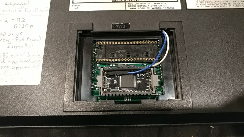
This is a version of Steven Adolph's REX Classic with a modified PCB design.
It is electrically identical to REX Classic, and uses the REX Classic firmware & software.
The PCB layout and shape are modified to:
- snap into a 3d-printed carrier to fit the Molex78805 socket
- provide connections for power and PORT_EN for programming the CPLD
Original version of this page, for building the original REX1
Parts & Materials
Note if ordering from PCBWAY: On the order page, you may have to manually change "Min tracks/spaces" to "6/6mil"
All tracks & spaces are well over 6 mil (everything is 0.2mm which is almost 8 mil), and that setting drops the price from $50 to $5
ENIG adds a lot of cost on PCBWAY and JLCPCB lately.
Currently the cheapest way to get an ENIG version for gold contacts (other than OSHPark) is Elecrow.
Upload the gerber zip from the releases, and manually select ENIG and Castellated Holes, and just use the cheapest shipping.
Other Compatible Flash Chips and how to identify them
Tools
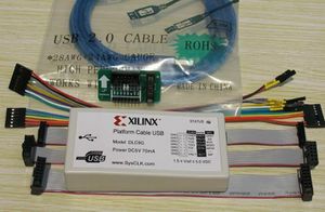
- Cheap Chinese clone is fine.
- Look at the pictures for ones that say model DLC9G, or DLC9LP. Don't put "DLC9G" or "DLC9LP" in the search, you will only get the overpriced ones.
- Get one that includes a "flying leads" cable, with separate loose individual wires on one end.
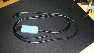
- A cheap usb-ttl cable is perfect. It's cheap, and already ends in loose wires with female dupont pins.
- Just use the red and black wires and ignore the rest.
- PC with at least one usb port, and a COM port or usb-serial adapter.
- Sandpaper, medium grit (120 or so), and a hard flat surface like a cutting board.
- Do not necessarily need anything fancy. I actually used this exact one to build a few REXs, although now I use a Hakko FX-888D with a T18-C2 tip.
- Or the strongest reading glasses you can get at a local drug store. 3.00x or higher.
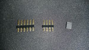
- 0.1" (2.54mm) pitch single row male pin header
- 1x6
- 1x4
- one shunt
- A Tandy Model 100, 102, or 200.
- Optional but recommended: Ultrasonic Cleaner and saponifying PCB cleaning solution and distilled or deionized water.
Software
- Xilinx ISE 14.7 Lab Tools
- Lab Tools is a subset of ISE. You can use either ISE or Lab Tools, but you only need Lab Tools to program the REX.
- This software is old and needs special futzing to make it work, no matter what OS you are using.
- Installing on Ubuntu Linux
- Installing on Windows.
- A TPDD_client to run on the M100
- There are several tpdd clients, and several ways to get one installed. These are a few options:
- For Mac, Linux, FreeBSD, any other unix: Get dl2 and use the bootstrap option to install TEENY.100 or any of the other options listed by "$ dl -l"
- For Windows: Get tsend.ps1 and use it to install TEENY.100 or any of the clients found at https://github.com/bkw777/dl2/tree/master/clients
- Play File:DOS100.CO.MP3 into the cassette port to install TS-DOS. (SOUND OFF:CLEAR 0,57089:RUNM "CAS:DOS100.CO")
- Get a real tpdd and bootstrap it's utility disk to install "Floppy".
- A TPDD_server to run on a modern host machine
- For Mac, Linux, FreeBSD, any unix: dl2
- For Windows: LaddieAlpha
- Start there, and follow the links to whatever is the latest "REX Release x.x Rebuild Package" zip file.
Procedure
Prep the Bare PCB
Lay a piece of medium grit (100-200) sandpaper face up on a hard flat surface like a cutting board.
Sand the edges of the PCB on the sandpaper just enough to clean off the panelization break-away points.
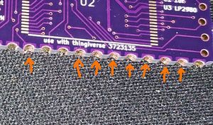
Use magnification to look closely at the castellated edge contacts for copper or gold "flags" hanging on the edge of most contacts. Scrape them off with an xacto knife.
Solder the Electronic Components
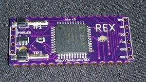
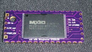
Solder these parts onto the matching labeled locations on the pcb.
- U1 = XCR3064XL
- U2 = 29F800
- U3 = LP2980-3.3
- R1 = 10K
- C1 = 1uF
- TP1 & TP2 = right-angle pin (optional)
Don't be too intimidated by the tiny legs on that TSOP-48 chip.
Just use magnifying glasses, lots of flux, and the DRAG TECHNIQUE.
Another example: https://youtu.be/09qb0KY_IF4
The TP1 and TP2 pins are only needed if you think you will ever perform the hardware modification required to use the main rom management feature. See FlexROM_100 or FlexROM_102 to facilitate this.
Clean the Finished PCB
Even "No-Clean" flux should still be removed as much as possible after soldering.
The best is to use an ultrasonic cleaner and saponifying pcb cleaning solution.
If you don't have that, then at least make sure your flux and solder are both "no-clean", and then use 99% isopropyl alcohol and a brush. This will still leave flux trapped under the chips no matter how much you soak it or wash it, but for no-clean flux it's not ideal but ok.
Program the CPLD
Now we need to flash the CPLD (Xilinx) with the .jed file. This configures the blank CPLD into a functional circuit that actually does something.
- Get the .jed file from here.
- Connect the jtag, 5vdc, and PORT_EN jumper.
Snap the PCB Into the Carrier
Flash the Firmware
Follow the REX 4.9 update directions to load the firmware onto the REX.
The original directions for that are here: 4.9 update directions.
Here are explicit/literal example directions to do that using dl2 on a Mac, Linux, FreeBSD, or other unix pc.
(For Windows: instead of dl2,
- Download & unzip the various files manually with a browser instead of cutting & pasting the wget & unzip commands.
- use tsend.ps1 for the bootstrap in place of "dl -v -b FILE.100"
- use LaddieAlpha for the TPDD server in place of "dl -v -u")
Back up any files off of M100. M100 will be wiped.
Cold reset the M100 (ctrl+pause+reset)
Power off the M100
Install the REX in the M100's Option ROM socket
Connect the serial cable between M100 and PC
Power on the M100
Install dl2 on a PC:
On the PC, in a terminal window.
$ git clone git@github.com:bkw777/dl2.git
$ cd dl2
$ make all && sudo make install
Install TEENY onto the M100:
On the PC:
$ dl -vb TEENY.100
Follow the prompts on the PC and on the M100 screen...
On the M100:
- BASIC
RUN "COM:98N1ENN"
On the PC:
- Enter
- wait...
On the M100:
- Enter
NEW
?HIMEM:CALL9643
- Look at the
Top: #####number. - A 32k machine should say 62213.
- Yours may say something else.
- Use that number in the following CLEAR command.
CLEAR 0,62213
MENU
On the PC:
- Enter
- should be back at a shell prompt now
Download the REX Classic setup files
$ mkdir rex_setup
$ cd rex_setup
$ wget http://bitchin100.com/wiki/images/3/38/R49_M100T102_260_rebuild.zip
$ wget http://bitchin100.com/wiki/images/6/63/M100_OPTION_ROMS.zip
$ unzip R49_M100T102_260_rebuild.zip
$ unzip M100_OPTION_ROMS.zip
Use dl2 to start a TPDD server
$ dl -vu
Copy RF149.CO to the M100, then run it.
On the M100:
- should be at menu
- TEENY.CO
> L RF149.CO
> Q
- should be at menu
- BASIC
CLEAR 0,55000
MENU
- should be at menu
- run RF149.CO
- Answer Y
- Wait...
- should be at menu
Reset the M100 to clear out TEENY and RF149.CO
- ctrl+pause+reset
- should be at menu, ram wiped
The flash memory on the REX is now formatted and loaded with REXMGR and a TS-DOS option rom image.
Install REXMGR from the REX itself
- BASIC
CALL 63012
- should be at menu, REXMGR should appear in menu
REX is now ready to use, and empty except for TS-DOS.
Now install an option ROM image. Example: Ultimate Rom II
- REXMGR
- press TAB once
- screen should say "TS-DOS* ------"
- press right-arrow once, highlight should move to "------"
- press F2
Loading from image filename: UR2100
Hit any key when TPDD ready.
Loading 0:UR2100.BX     ####
- now it should say "TS-DOS* UR2100 ------"
UR2 is now loaded into REX, but not currently selected/active, TS-DOS is.
What this means is, If you were to go back to BASIC and run CALL 63012 right now, it would load TS-DOS, as if you had a TS-DOS option rom in the option rom socket.
To run UR2, you have to select it in REXMGR first.
- right-arrow to highlight UR2100
- press enter
- Y
UR2 is now the active option rom image. Additionally, the equivalent of CALL 63012 was already done for you by REXMGR just as a convenience to skip a step.
F8 back to menu.
Leave dl2 running on PC while you load more rom images.
Ctrl+C to exit dl2 when you're done with it.
Done!
That was the last step. You're done! Consult the REX docs to start using it!
Main ROM Management
- For 100, see FlexROM_100
- For 102, see FlexROM_102
- For 200, no FlexROM for 200 yet. See the regular REX docs.
References
KiCAD source files for the PCB
OpenSCAD source files for the carrier
Version c6 pcb This version of the pcb is obsolete, but has pics of the firmware flashing process.
Version c8 pcb This version is also now obsolete, but the only difference is the pcb dimensions and matching carrier.
